Kiosk Setup Guide
This article provides step-by-step instructions for assembling the VeronaPOS Kiosk and its floor stand. Proper assembly ensures the kiosk is structurally sound and that all cables for the power supply, network, and card terminal are securely connected for optimal performance.
For video instructions, click here: Kiosk Assembly Instruction Video
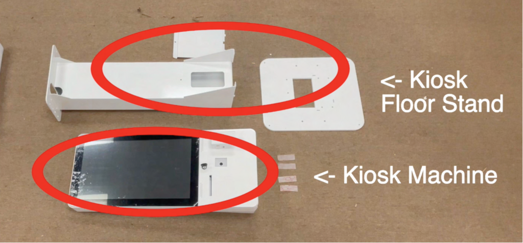
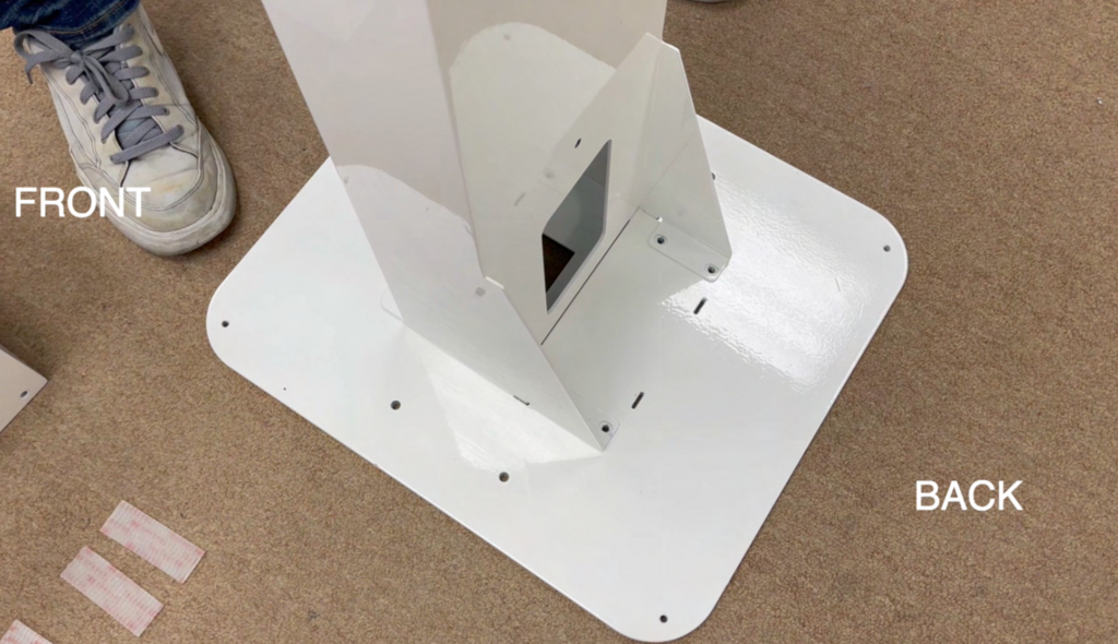
Begin with the Kiosk and Stand parts.
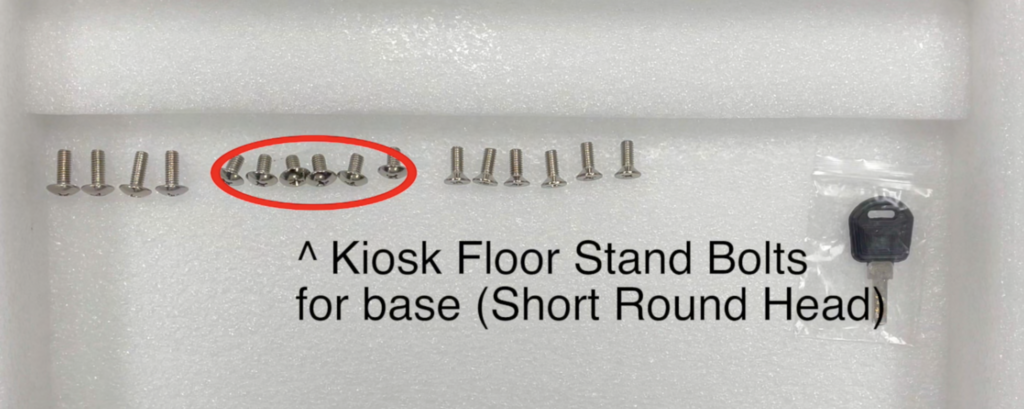
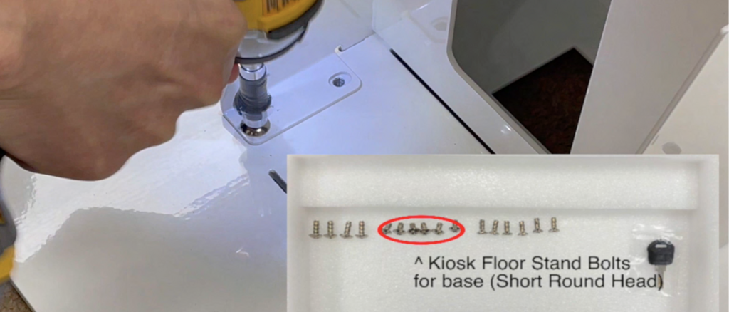
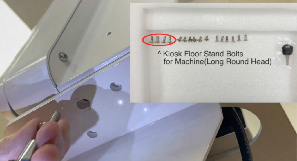
Bolts required for assembly.
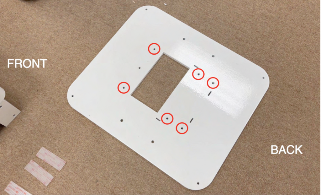
Kiosk Floor Stand Base. This is a very heavy panel. Bolts will be screwed into the 6 circled holes shown below.
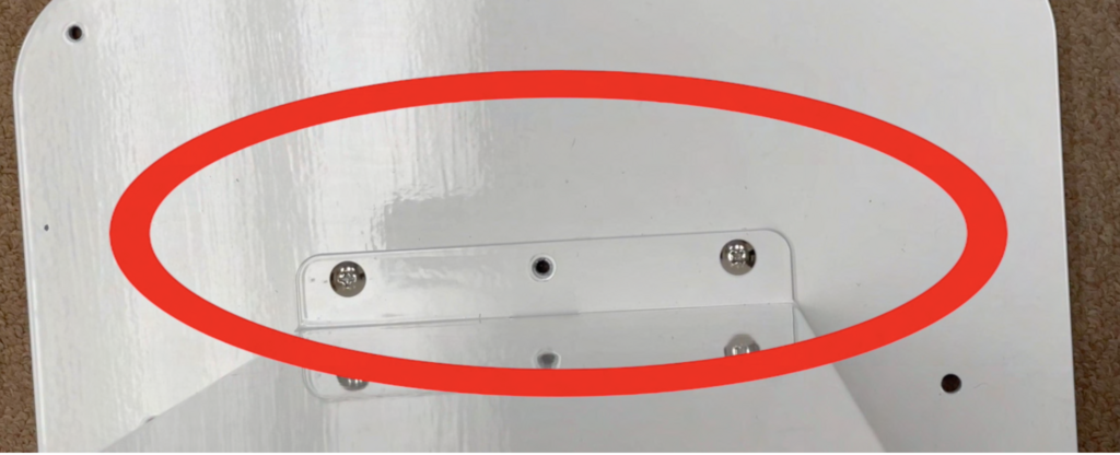
Place the stem on top of the base. Ensure the holes on the stem align with the holes on the base panel.
Use the short, round-head bolts to fasten the components. Only 6 are provided, so ensure you screw them into the circled spots mentioned previously.
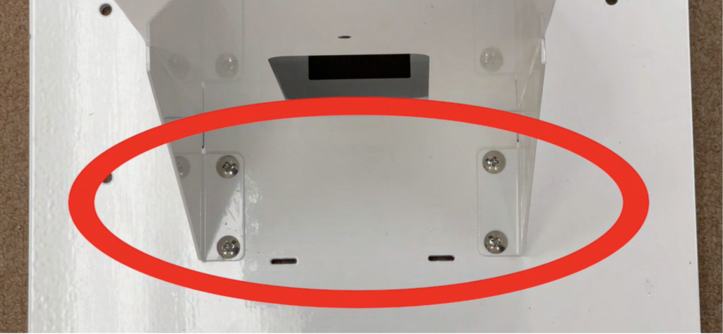
Bolt placement for the front and back of the base.
The Kiosk machine is shipped with the LAN and power cables already attached.
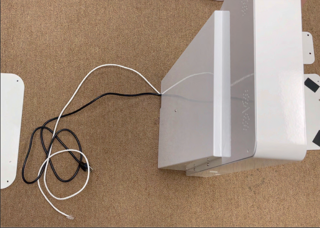
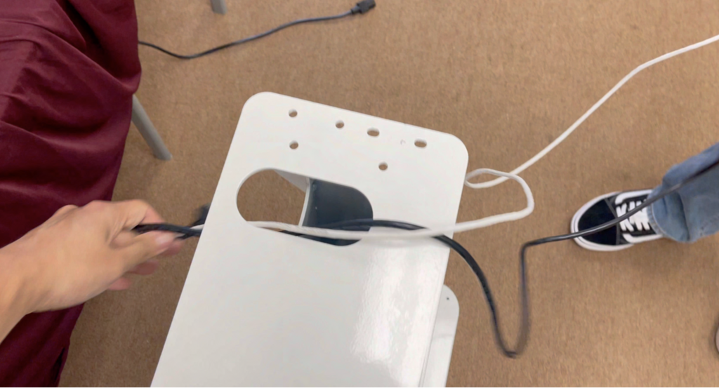
You can use the access hole to hide the LAN and power cables if needed. They can also be routed through the hole at the bottom of the stand stem.
Align the hole on the Kiosk with the hole on the top base of the stem.

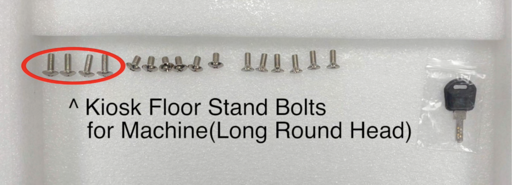
Screw in the 4 long, round-head bolts (2 on each side).
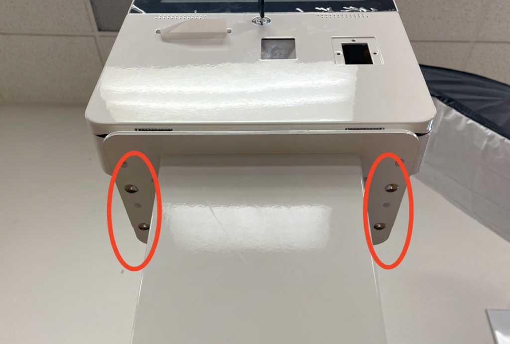
This completes the structural assembly of the stand.
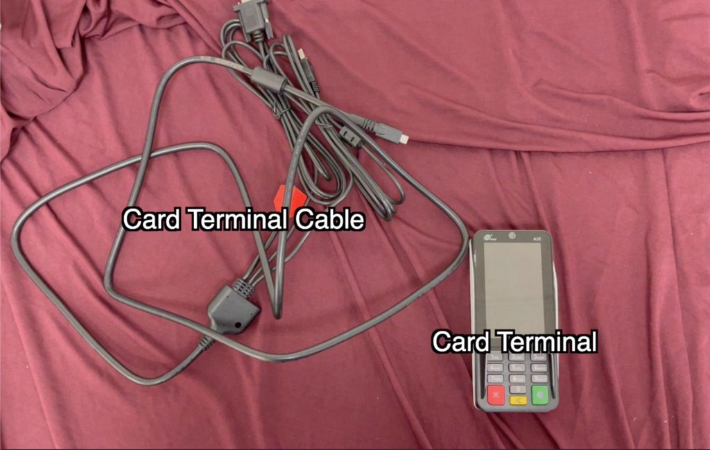
Card Terminal Assembly
The card terminal assembly is the next step.
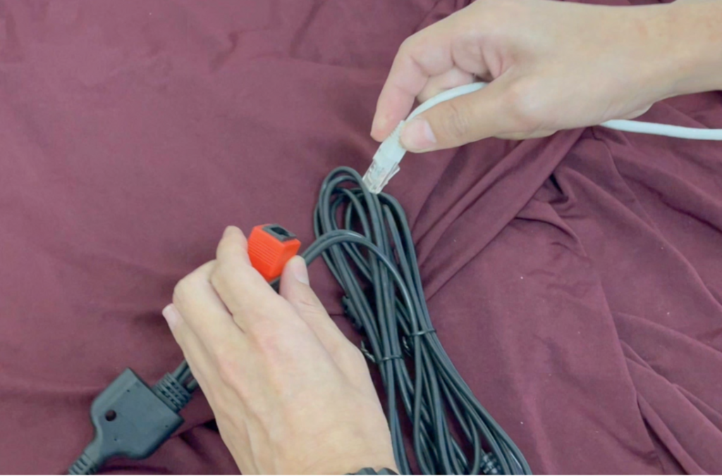
The LAN cable must be connected to the terminal and then to your router.
Note: Two separate LAN cables should be connected individually, one to the Kiosk and one to the Terminal.
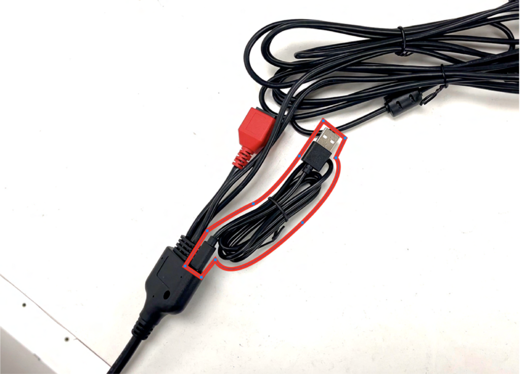
Power for the card terminal is connected via a USB to USB-C cable. Please connect it to a USB power supply.
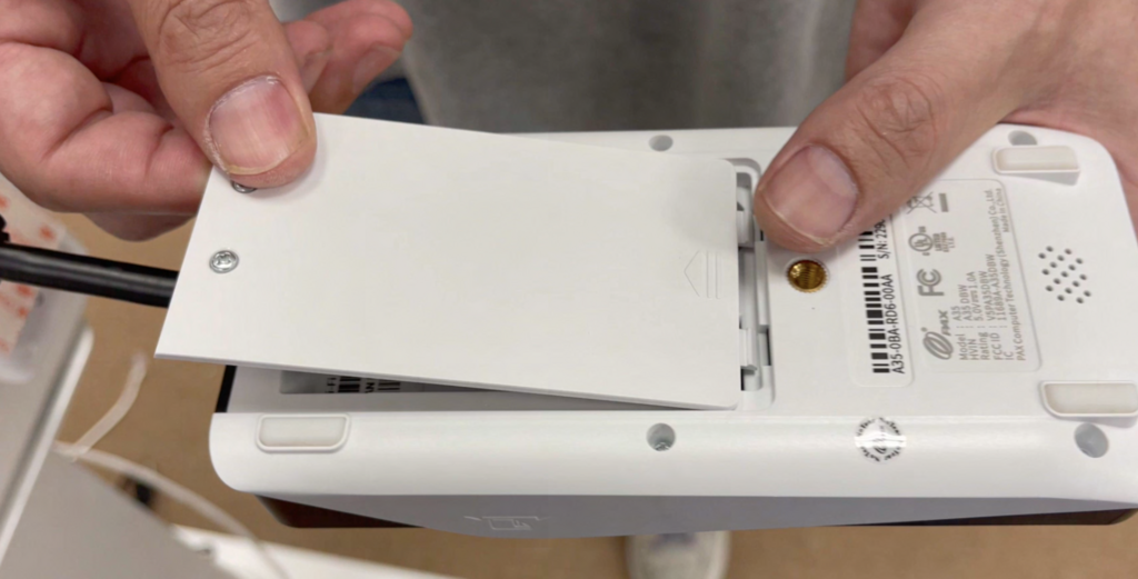
To connect the card terminal cable, first open the Kiosk case.
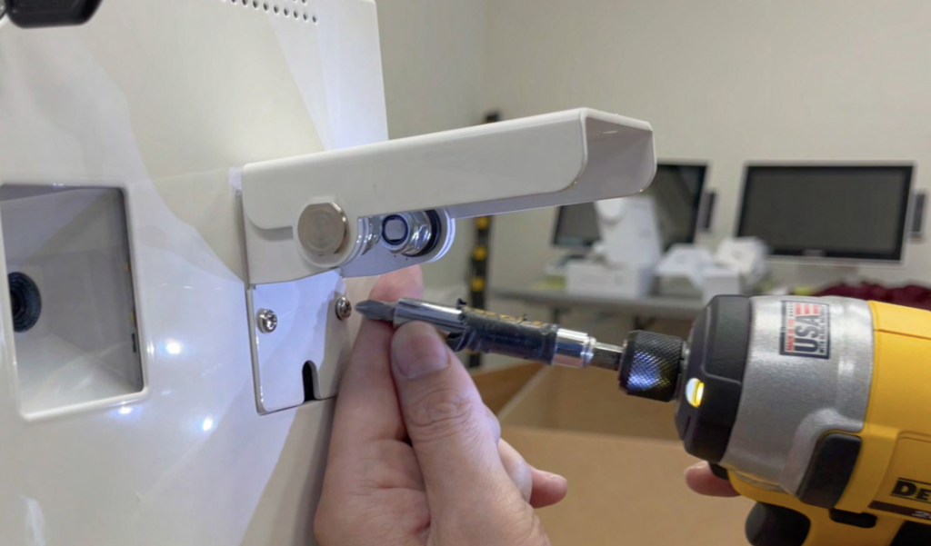
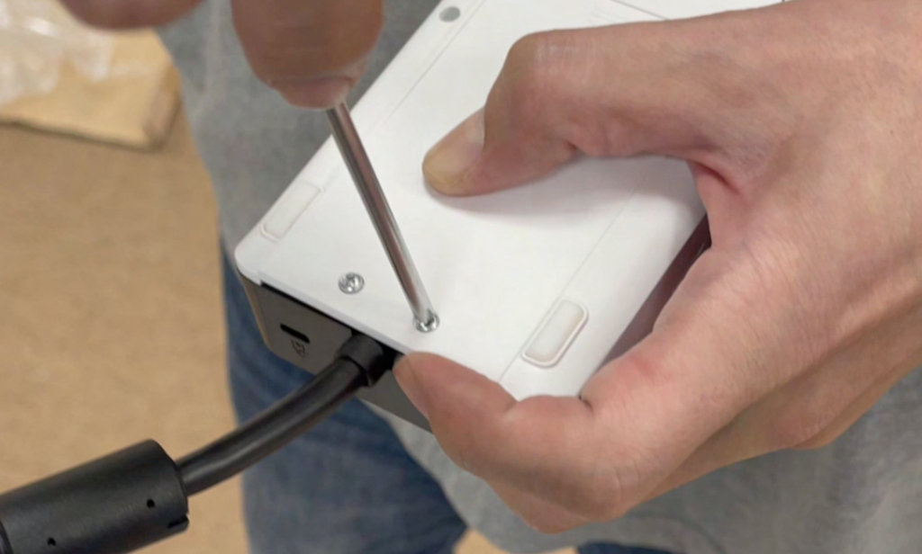
Unscrew the card terminal pinpad mount. There is one bolt inside the case and two bolts on the outside.
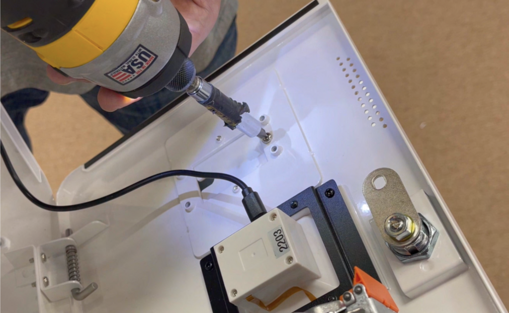
Here are the two bolts located on the outside.
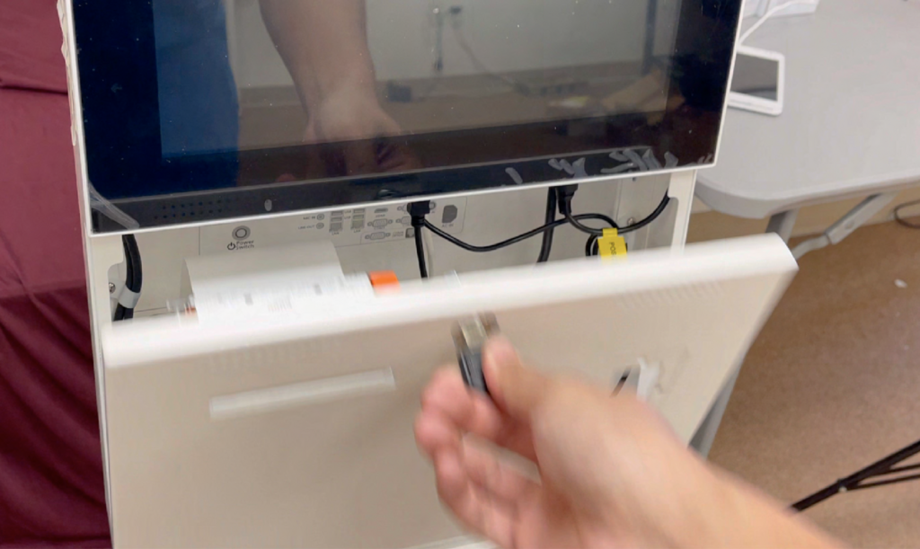
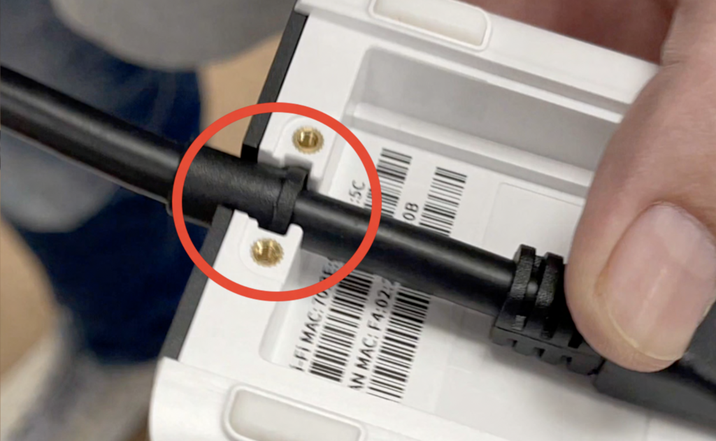
Route the USB-C cable toward the front of the kiosk through the hole in the back.
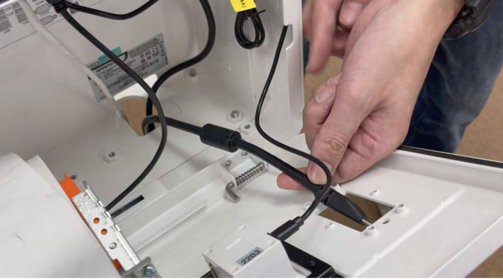
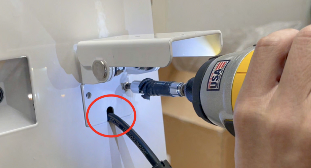
Reattach the mount, allowing the cable to run through the small gap in the mounting bracket.
Unscrew the back of the card terminal and remove the back panel.
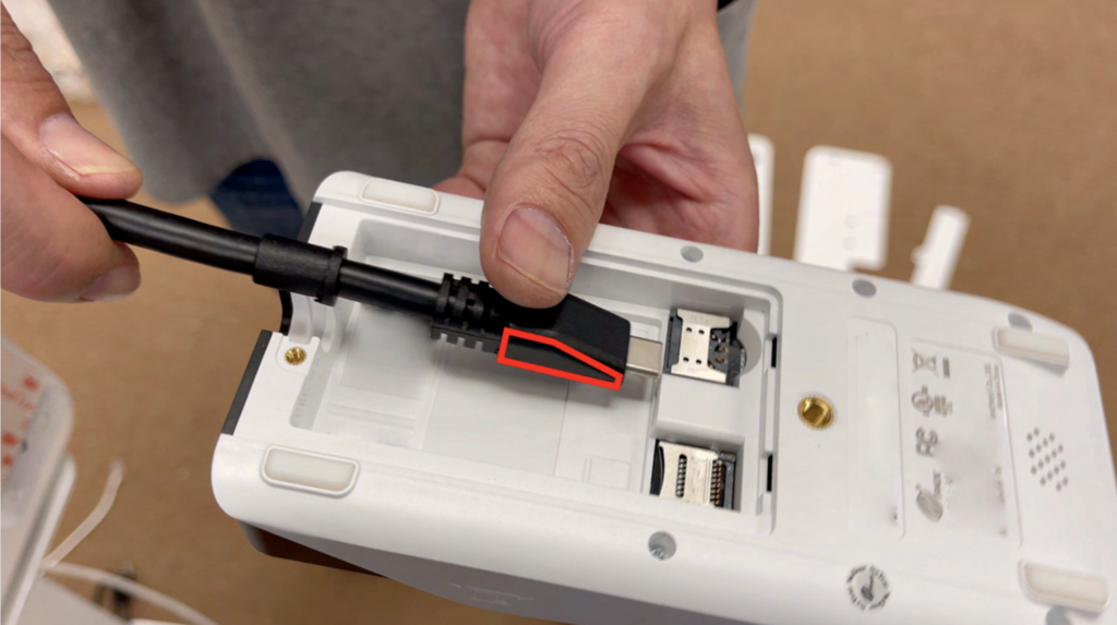
Connect the USB-C cable to the card terminal. Ensure the wedged part of the connector is facing up.
Ensure the back cover is placed correctly.
Screw the cover back into place.
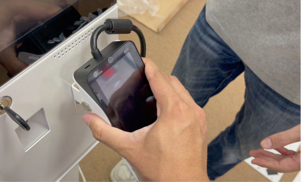
Peel the film from the fastener strip and attach the card terminal to the top of the mount.

Secure the terminal in your preferred orientation.
To power on the kiosk, press the power button located inside the case in the front-left corner.